This website stores an open database of piezo-actuated and -received guided waves (GWs) signals propagating in a composite panel of a full scale aeronautical structure. The composite panel closes the bottom part of a wing box that, along with the leading edge, the trailing edge and the wingtip, form an outer wing demonstrator of approximately 4.5 meters length and from 1.2 to 2.3 meters wide.
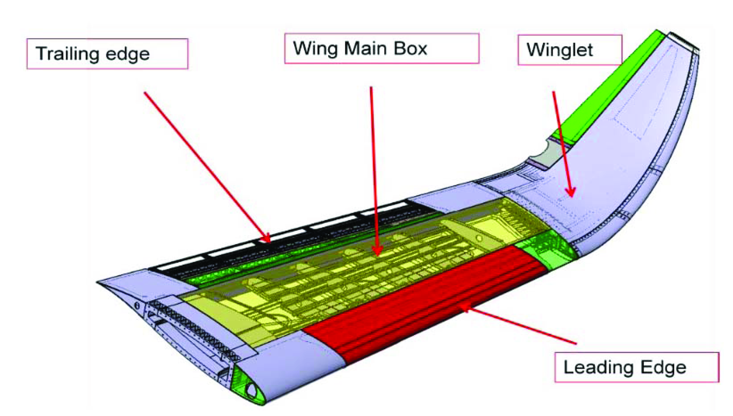
To
create the database a Structural Health Monitoring (SHM) system,
composed by a SW/HW central unit capable to control a network of
160 piezoelectric transducers secondary bonded on the composite
panel, has been realized. The SHM system has been designed to (i)
perform electromechanical impedance (EMI) measurement at each
transducer, in order to check for their reliability and bonding
strength, and (ii) to perform an active guided wave screening for
damage detection. More details are available in the following
paper:
Marzani, A., Testoni, N., De Marchi,
L., Messina, M., Monaco, E. and Apicella, A.,
An open database for benchmarking guided
waves structural health monitoring algorithms on a composite full-scale outer wing demonstrator.
Structural Health Monitoring (2019). https://doi.org/10.1177/1475921719889029
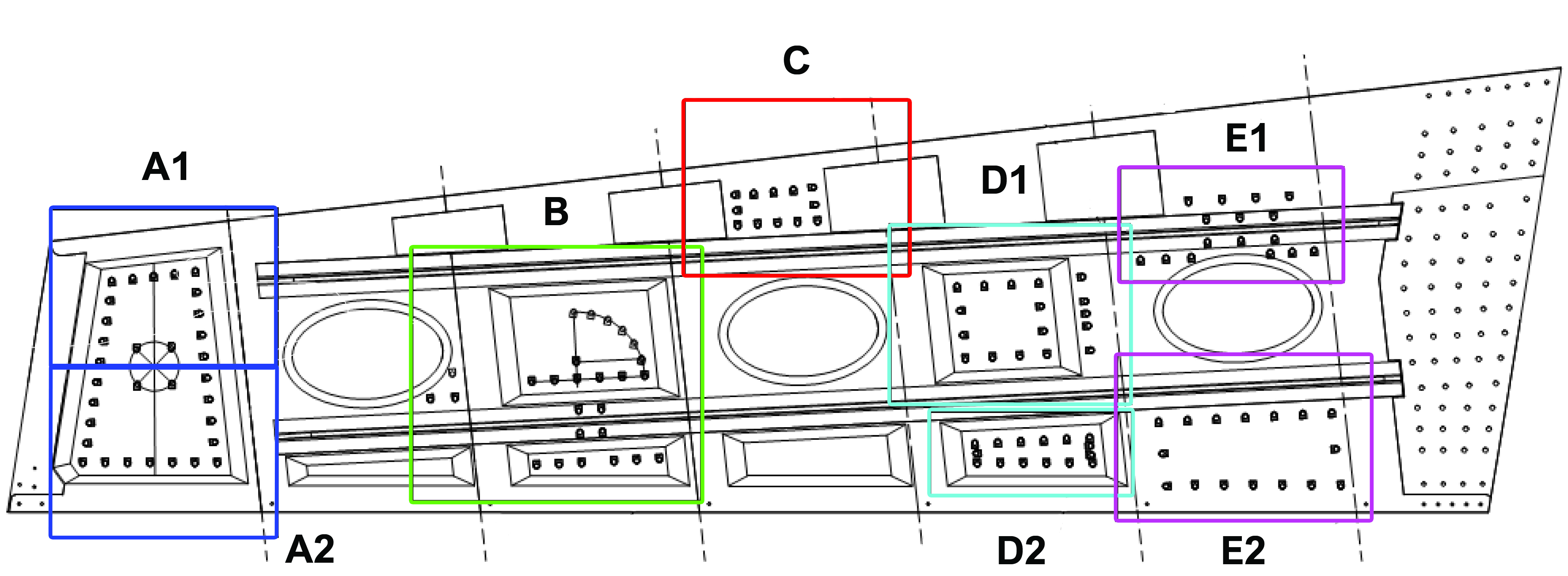
The lower part of the wing has been divided different bays (A, B, C, D = D1 + D2, E = E1 + E2), each with a different number of sensors.
For each of the following groups and sub-groups (A, B, C, D1, D2, E1, E2) a text file is available here. Each file provides for each sensor (Aj) or bay vertex (Vj) a label (Sn), its Y position (dY) in [mm], its X position (dX) in [mm], the sub-section number (S) and for each sensor the sensor number (Nr). A detailed description of the geometry and sensor positioning is available in this pdf.
Data have been collected for different testing scenarios, namely on the single lower wing composite panel lying on a laboratory table in static condition (T0); after assembling the lower wing panel into the composite wing box which was hanged in a cantilever configuration to a metal fixture (T1); after a fatigue test protocol in which the wing box hanged on the metal fixture undergone to 90000 flexural cycles (T2); and finally after the wingbox hanged on the metal fixture was impacted from the bottom by a controlled air gun (T3). The detailed description of these phases can be found in the Proceedings of the research project SARISTU.
To obtain a link for downloading a separate zip for each timeline, please send an email to both the following address:
Replacing (dot) and (at) as
appropriate.
Inside each timeline zip file, the data are divided in the following subdirectories: